From Robert Meade, SARA mailing list 24/12/2025:
Rather than using Dicke switching of the RF path between the antenna and a resistor as a noise source with PIN diodes, physical relays, or solid state relays, an alternative is to consider very low insertion loss 20+ dB isolation directional couplers fed with an active noise source of known noise power and spectral characteristics. It seems that a noise diode input to one of these should be more of a 0.2 dB noise figure impact vice 1 to 2 dB for putting any of these types of switches in front of the first LNA stage. These would also likely integrate easily into the connectorized loop feed + SAWBird+H1.
If cost is the driver, used directional couplers can be found cheap on the used market, and a fancy lab noise diode source need not be used, but a cheap noise generator board should suffice. Even without lab test equipment, MIT SRT’s over the air noise diode calibration method suggests absorber foam can be used to characterize the noise source and then it can be used without any motorized absorber foam system to do reference switching.
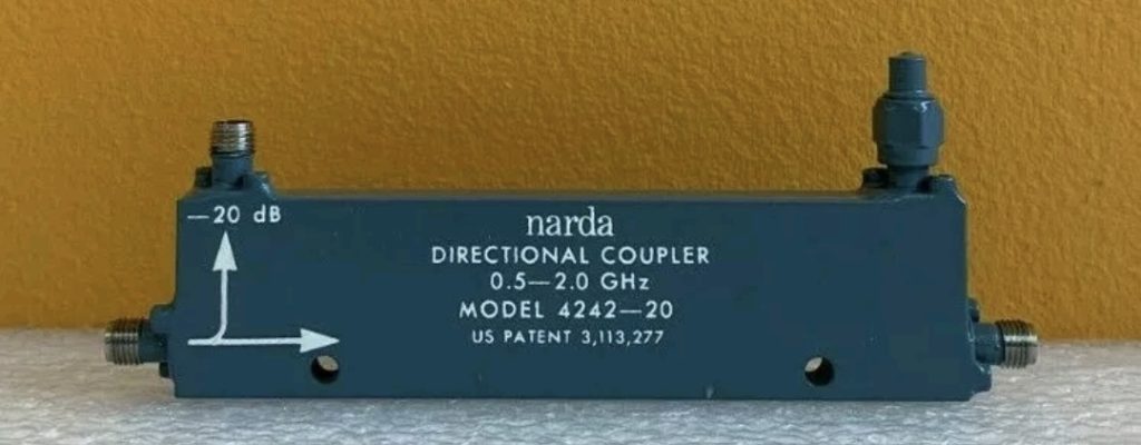
20 dB directional coupler covering 1.4 GHz:
https://www.ebay.com/itm/234565272708
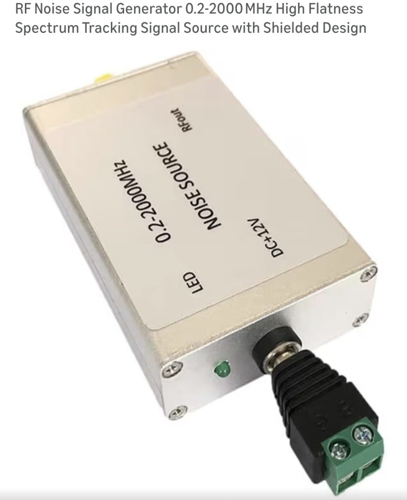
Noise Generator covering 1.4 GHz (Ignore the seller’s false “tracking generator” marketing presumably to appease the amazon compliance folks):
Robert
Jim,
I agree it’s not the Dicke switch schematic if using a directional coupler and switching on and off an injected reference. Thanks for keeping me straight on the semantics there.
To that point though, the SRT over the air (OTA) noise diode isn’t a Dicke switch either, and one could argue that neither is motorized absorber foam blocking a dish feed as well, even if it achieves the same function of “switching” between signal and self-contained reference.
Is there a meaningful difference for our application between an on/off noise reference injected over a directional coupler and an actual Dicke switch for our application of acquiring HI radiometer reference spectra? I guess the switch method removes all external noise sources from calibration, as should the RF absorber foam in practice. MIT seems to deal with the additional noise inputs for an OTA noise diode calibrator using an empirical approach.
MIT SRT Calibrator: https://web.mit.edu/8.13/www/nsrt_software/Calibration/SRTcalibrator.pdf
Andy,
A directional coupler is a device which allows RF to pass along one path in either direction with very low insertion loss while tapping off a reference signal at a reduced power level consisting of power flowing in only one direction. Commonly this reduced level is 6 to 20 dB down from the main path power level. Directional couplers can be used to inject reference signals with some level of attenuation into the RF path as well as tapping off power in one direction from reflection off of a mismatched load. Because of this, they are often used to measure reflected and forward power in order to calculate VSWR or S11 magnitude. I had good success using 2nd hand ones for low cost VSWR measurements of 5.8 GHz antennas before COTS SWR meters were affordable at that frequency. They are also critical to using a spectrum analyzer with noise source or tracking generator to make S11 measurements of microwave devices.
Here’s an example of use for VSWR measurements at 5.8 GHz: https://www.youtube.com/watch?v=F69ZKZZhd-k
Spectrum Analyzer use w/ Noise Source: https://www.youtube.com/watch?v=SP8u0ceGs0Q&list=PLynuGts93wlBOOu-Jmgf-fH-tb1pvp1lZ&index=15
And microwaves 101 is always a good resource for more info: https://www.microwaves101.com/encyclopedias/directional-couplers
Robert