Hi Andy,
You recently asked a question on the SARA forum
“I notice that the SETI Horn of Plenty is a smaller version of the original Ewen Horn that first detected hydrogen in Milky Way in 1951 – how do horns scale? I’ve tried to look this up on line and can’t get a clear answer – clearly the first part of the antenna near the waveguide is set regarding its measurements – what commercial makers call the coax to waveguide adapter – this has set width and height. However, the horn section that follows until the aperture – can you simply be scaled by any amount from the SETI Horn of Plenty design or does this need to be in exact numbers of hydrogen wavelengths or some other way of scaling the horn?”
Don’t know if this will help but here is my twopenny worth.
When I built my horn and because I didn’t know any better I just blindly copied dimensions as described in the Harvard-Smithsonian paper here. Copy also attached
https://lweb.cfa.harvard.edu/~npatel/hornAntennaAASposterPDF2.pdf
I’m sure you have seen this. My horn was based on these dimensions and as mentioned seemed to perform well

Later I found a McMaster University paper ‘Lecture 18 Horn Antennas’ which I am sure you will also have come across. https://www.ece.mcmaster.ca/faculty/nikolova/antenna_dload/current_lectures/L18_Horns.pdf Copy also attached.
The paper whilst very interesting is rather maths heavy and I don’t pretend to understand all of it but there seem to be a few key equations
Using the nomenclature shown in the diagrams on page 16 of the pdf.

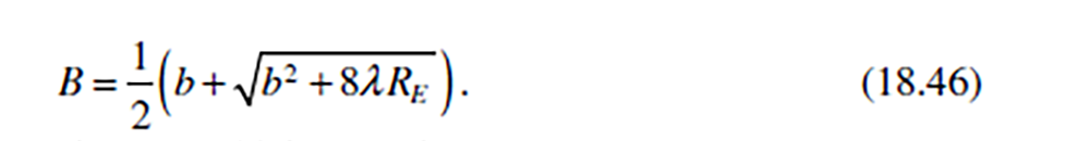
and on page 14 the equation

On my horn, using the Harvard design, the B and Re dimensions conform to both of these equations. To consider the effect of scaling, Equation 18.46 does contain a square root function but if I use 18.46 to plot a curve of Re against B I get what looks to be a straight line.

So you would think that scaling a design to any length of Re shouldn’t be a problem as long as the relationship described in 18.46 is maintained.
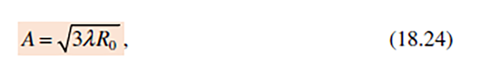
The McMaster paper also gives an equation for dimension A on page 8
and on page 16 a relationship between Rh and A as
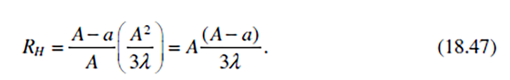
This is clearly a rather more complicated parameter and a little beyond by maths and indeed in some discussions in the paper go on to hint at this. Checking my horn dimensions though I found that assuming Harvard dimension I used for A of 74.4cm, and then plugging this into formula 18.47, the calculated value of Rh is then 67.9cm which is not that far off from to the 69.5 Harvard dimension I used. I am not sure of the reasons for this discrepancy but at just 1.6cm it doesn’t seem that significant – just 2.3% of the length
To go back to your original question, I suspect – as Adrian has also mentioned – that as long as you maintain the wave-guide cross section dimensions and then scale the A, B and Rh dimensions as required, checking back to align with equation 18.46, you shouldn’t be that far off.
As far as scaling to multiples of 21.1cm goes, the McMaster paper seems to make no reference to this. However although the Harvard Rh, Re and B dimensions don’t seem to contain multiples, the Harvard H-Plane Ro dimension of 84.5cm is an almost exact 4 times multiple of 21.1 (84.5/21.1= 4.0).

The open aperture diagonal dimension of 94.95cm is close to a 1/2 multiple of 21.1 at 4.52 (94.95/21.1 = 4.52)

Similarly, the Harvard H-plane ‘A’ dimension of 74.4 is also close to a 1/2 multiple of 21.1 (74..4/21.1 = 3.52).
I don’t know if these are all just coincidences or are significant but its probably worth noting this all the same and may be worth considering in any design.
I should caveat all this by saying that I am no authority on the subject and its probably best to listen to people that really do know what they are talking about. I have just built one horn and have read a couple of papers on the subject but as mentioned I was very impressed with my Harvard dimensioned horn and at one point considered scaling it up before deciding in the end to go instead for a bigger dish. Construction took some thinking about how to get the panel dimensions needed. I ended up building a CAD model to do this. One thing that did surprise me that was exposed by the CAD model – and indeed came true during the build – was that the angle between horn panels is 97 degrees not 90 degrees gas I had assumed. Maybe in a metal sheet/metal angle build this can be addressed with a bit of judicious bending!
Anyway it will be interesting to see how you get on. Be sure to put in a few drainage holes into the end of the wave guide as the horn makes a very efficient rain water collector!
Dave
Dave Bracey