Our intention is to design a cantenna where fine tuning can be achieved experimentally in the same device without needing to re-make the cantenna or physically cut bits off the monopole probe within it to achieve better performance. These ideas are based on the way that a Dobsonian optical telescope can be aligned in the field.
Our current plan is to make the monopole out of a threaded 99% copper rod, which then threads into a non-conductive block, which itself attaches to the cantenna via a groove – so that the rod can be lengthened or shortened inside the cantenna and the distance from the monopole to the rear of the cantenna can be varied in the groove (both are important measurements in cantenna tuning).
https://www.astronomy.me.uk/wp-content/uploads/2025/12/Cantenna-Isolated-Antenna-Assembly.pdf
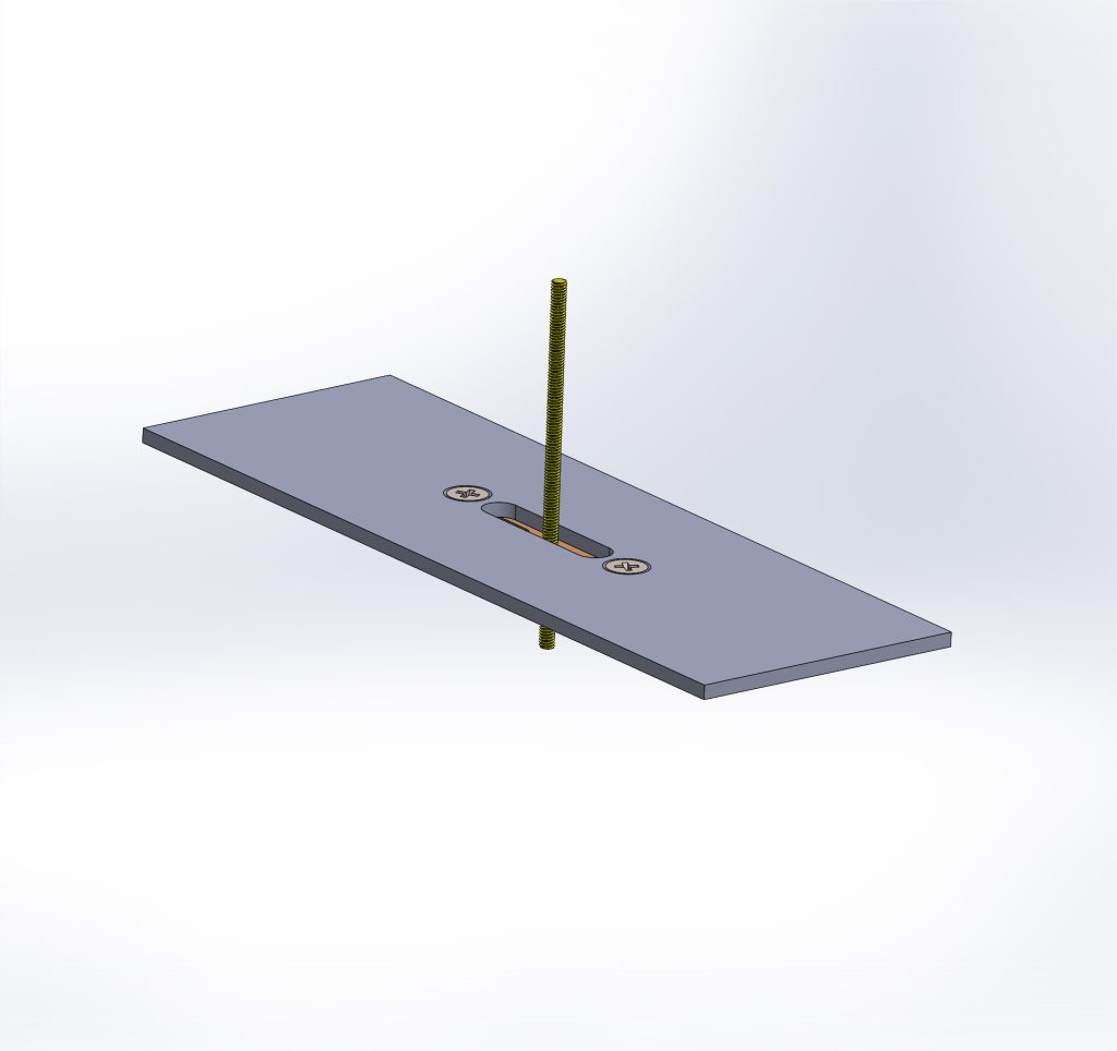
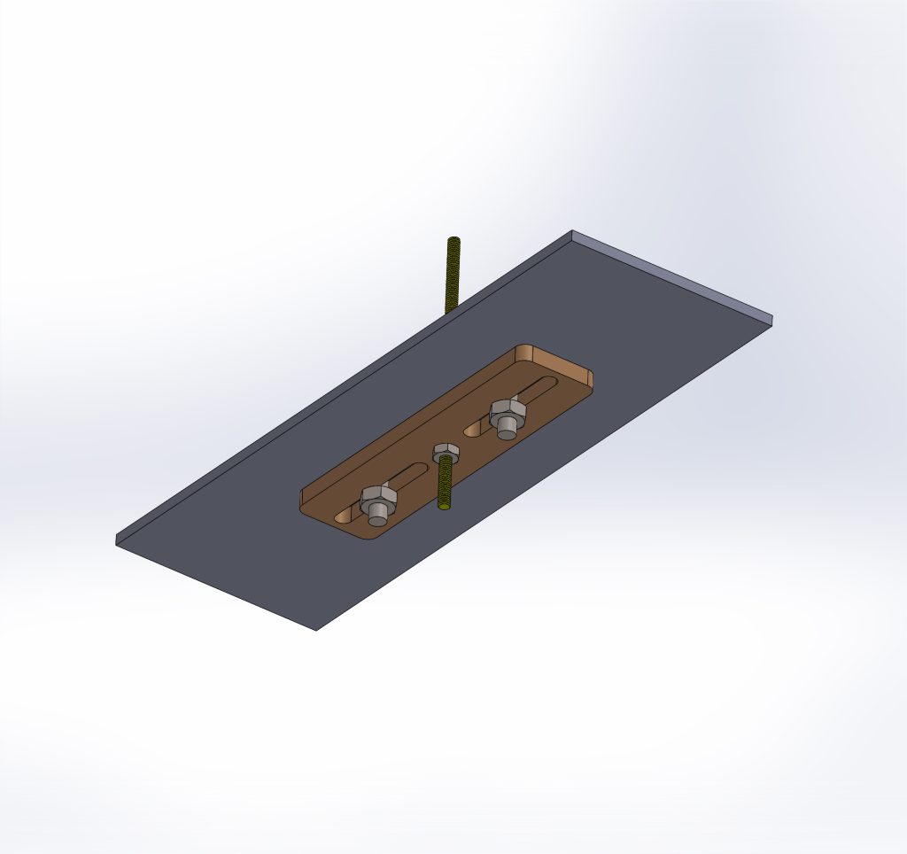
Very nice CAD drawings. I think the coax connection detail as Ted mentioned needs addressing. Possibly rather than the threaded rod just a regular TNC etc coax. connector and for the probe concentric brass/copper tubes soldered to the connector center pin so that an inner tube inside the solderded outer one can be slid in or out for the 1/4 wavelength tuning.length. Perhaps also the open slot may alter the cantenna characteristics. What if the slot was covered with a sliding metal piece containing the coax connector assembly and the piece has slotted ends such that bolts on the slots attach it to the cantenna side and if loosened then the metal piece can be moved forwards or back along the inner opening and then the bolts retightened after
VNA adjustments and all along the metal piece still covering electrically the open cantenna slot on its side. Hope the explanation is not too confusing, the main idea is that possibly an open slot on the cantenna side will be detrimental to the waveguide characteristics so a sliding metal piece along the side covering it would prevent this possibility.
Adrian
Adrian Clausall
I think the CAD drawing that Julian made is perfect. My suggestion is instead of the insulating sliding piece, make it out of metal so the electrical surface of the cantenna/waveguide remains intact by using copper or brass for better outdoor exposure. So just replace the threaded rod in place with the coax connector so the whole assembly may be adjustable. As far as the monopole probe, possibly just a length of smaller tubing shorter than the intended 1/4 wavelength soldered to the coax connector center terminal post and then fiting it with a slightly larger outer diameter snug tubing section that can be slid longer to adjust for the tuning could work. Ideally someone good at using either 4nec2 or EZNEC either packages, could possibly model the additions and see what the result will be.
I think this will make for an excellent upgraded design for the cantenna optimization tuning. I think I might try to kludge something at least partially like it when trying to make mine eventually.
Adrian