Note some of the following is based on AI search results and has not been fully confirmed. So please check other data sources before using this content in your own system.
Principle behind the design:
Reversing the perspective: First and foremost, the conceptual approach is reversed. It is not that “the components of a geodesic structure form a natural parabola,” but rather that we “identify” a geodesic structure on the surface of a pre-defined parabola.
Approximation of the surface: The fundamental principle of the Geodesic Parabolic Dish Antenna is to approximate a parabolic surface using multiple planes. This is the same principle used in any antenna where mesh is attached to a frame.
Definition of a plane: A plane is uniquely defined by three points, not four. Using four points would result in two intersecting planes.
Triangular composition: Consequently, the parabolic surface is composed of a collection of triangles.
Structural efficiency: While the edges of these triangles form the structural ribs, it is highly advantageous if the shared edge of two adjacent triangles can be formed by a single rib. Please note that in a typical Geodesic Dome, the edges of adjacent triangles are often separate components.
Choice of material (Flat bars): To form a triangle, three ribs must intersect. Considering the connection and the thickness at these intersections, using flat bars is the optimal choice.
Constraint of geodesics: A flat bar, which can only bend in the direction of its thickness, must follow a “geodesic line” to conform to a parabolic surface.
The design process: My design begins by “identifying” geodesic lines on the parabolic surface, initially positioned at 120-degree intervals.
Engineering advantages: At the intersection of flat bars along these geodesic lines, the surfaces of the bars meet at a perpendicular orientation. This allows the faces of the flat bars to fit tightly together, which is a significant manufacturing advantage.
Unique determination of length: Once the vertices of the triangular segments (the intersection points of the flat bars) are identified on the parabolic surface, the lengths of the triangle’s sides are uniquely determined.
Formation of the parabola: By joining the flat bars according to these uniquely determined triangular dimensions, the intended surface—the parabola—is naturally and uniquely formed.
References: For a better understanding of geodesic lines, I recommend this video: The Nature of Geodesics (https://www.youtube.com/watch?v=m6WY6VtPYrk).
Further reading: I encourage you to read all the references listed in my Design Chart: http://www.terra.dti.ne.jp/~takeyasu/GeoParaAnt_9.pdf
I hope this explanation helps your understanding.
Regards.
Yoshi Takeyasu, JA6XKQ
This is a reproduction of Yoshi’s post on SARA Mailing List.
Yoshi’s design chart can be accessed at http://www.terra.dti.ne.jp/~takeyasu/GeoParaAnt_9.pdf
_________________________________________________________________
Reply from Henri on SARA Mailing List:
Hello Andrew,
The rods tied together are not forming a natural paraboloid. As Yoshi mentioned, it works the other way around.
You start by stating the characteristics of your parabolic reflector: D and f. Then you try to lay down on its imaginary surface the curves which, tied together, will create the skeleton of the paraboloid. Among ellipses and parabolas, some curves have the ability to stick nicely to the surface because each point of those curves is tangent to the surface of the paraboloid. They are the geodesics of the paraboloid. They carry the ultimate ability to “wrap” the surface very smoothly. By choosing them judiciously, you can distribute the geodesic curves regularly over the surface, avoiding concentration and dispersing the stress all over the mesh. The mesh can be triangular or squad.
The parameters of the paraboloid targeted, the choice of distribution of geodesic curves over the surface and mathematical calculations which translate the wrapping ability of the geodesic curves will produce the coordinates of the points where they cross each other.
I hope this helps to answer your question. Please just ask if you need more.
Regards
Henri Nicot
______________________________________________________________________________________
Following added by editor:
Information below is provided for reference only – the code examples have not been tested and no warreny is provided related to their use for any reason – use entirely at your own risk and check the code independently before using it.
Python coordinate transformation paraboloid to w-y plane:
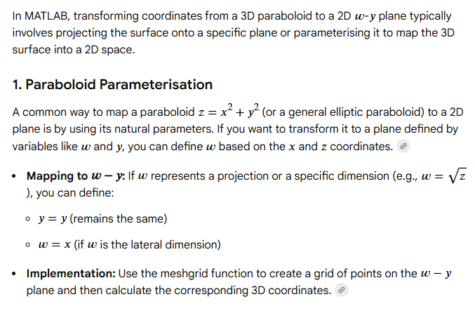
To transform a paraboloid into a flat plane (the
w-y plane), you typically employ a “flattening” or projection method. In Python, this is often handled by projecting 3D points:
(𝑥,𝑦,𝑧) onto a 2D surface based on the paraboloid’s equation, usually:
𝑧=𝑎𝑥2+𝑏𝑦2.
Transformation Logic
Mapping a paraboloid to a 2D plane (like w-y) usually involves one of two goals:
- Orthographic Projection: Simply dropping the
𝑧-coordinate, where
𝑤=𝑥 and
𝑦=𝑦.
- Surface Parameterisation: Mapping the curved distance along the surface to a flat grid.
Python Implementation with NumPy
Using NumPy is the standard way to handle these matrix-like coordinate transformations efficiently.
python
import numpy as np

# 1. Define your paraboloid surface (e.g., z = x^2 + y^2)
x = np.linspace(-5, 5, 100)
y = np.linspace(-5, 5, 100)
X, Y = np.meshgrid(x, y)
Z = X**2 + Y**2

# 2. Simple Projection to the w-y plane (where w = x)
# This effectively "squashes" the 3D surface onto the plane
W = X
Y_plane = Y

# 3. For more complex surface unwrapping, you might use distance along the arc
# Arc length of a parabola: s = integral(sqrt(1 + (dz/dx)^2) dx)
# Below is a simplified linear mapping for visualization
transformed_coords = np.stack((W, Y_plane), axis=-1)
Use code with caution.
Advanced Tools for Geometry Transformation
- OpenCV (cv2.projectPoints): Ideal for projecting 3D points from a paraboloid onto a camera’s image plane.
- SciPy (curve_fit): Useful if you need to determine the paraboloid parameters from raw 3D data before transforming them.
- pyRANSAC-3D: A specialized library for fitting and extracting geometric primitives like paraboloids from point clouds.
Coordinate Conversion Libraries
If your “paraboloid” is actually an ellipsoid (like Earth’s shape), use PyProj to transform coordinates from a curved geographic system to a flat “state plane” (x,y) system.
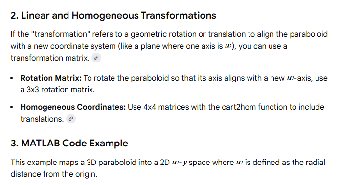
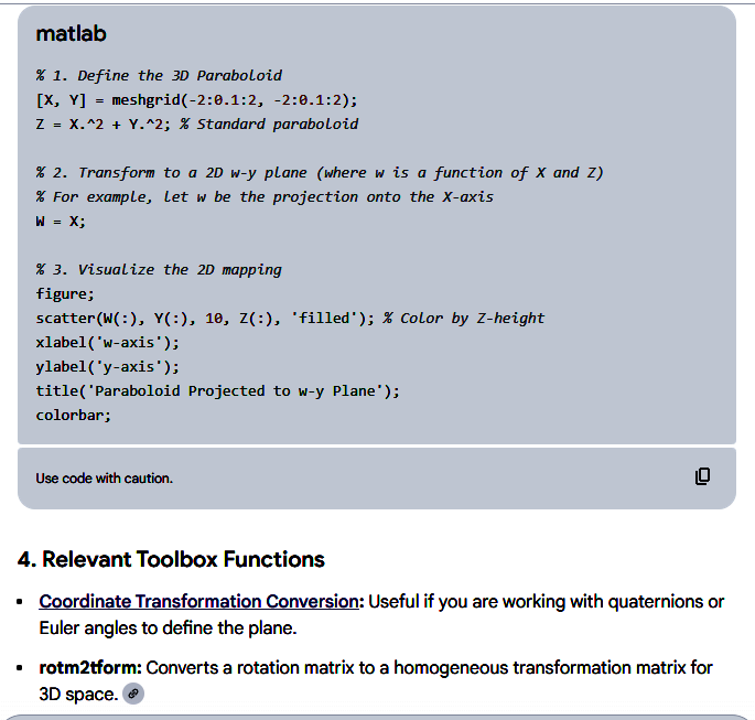
matlab coordinate transformation paraboloid to w-y plane:
Please make it clear that you are quoting my post on SARA and cite the source of “my Design Chart.” http://www.terra.dti.ne.jp/~takeyasu/GeoParaAnt_9.pdf
No problems – will change it now!