Dr Andrew Thornett
Lichfield Radio Observatory – www.astronomy.me.uk
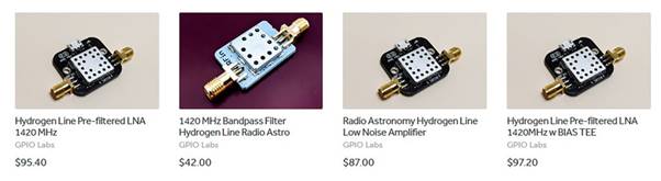
GPIO Labs produces a selection of filters and low-noise amplifiers designed specifically for observations of the neutral hydrogen spectral line at 1420 MHz. These products are intended for amateur and educational radio astronomy applications. The current range consists of four primary options (prices may vary between suppliers).
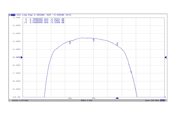
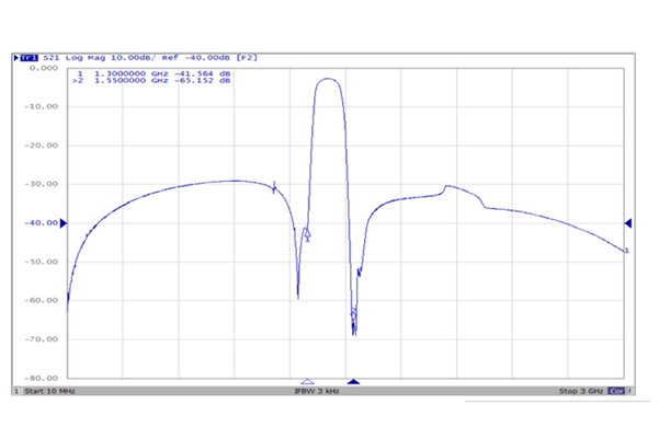
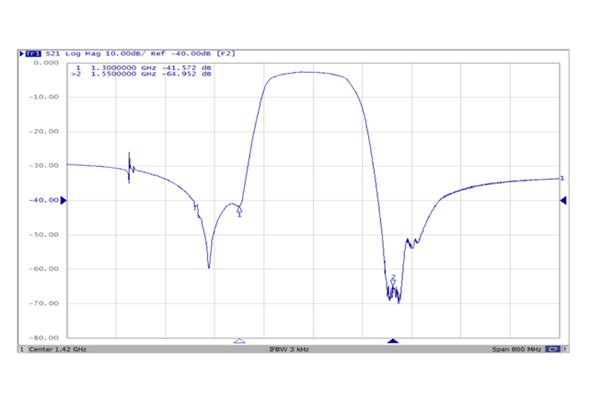
1420 MHz Hydrogen Line Bandpass Filter
This compact, economical filter is centred on 1420 MHz and is intended to isolate the hydrogen line region. The typical insertion loss within the passband is approximately 3 dB. Unlike enclosed commercial units, this version is supplied without a protective housing.
The unit tolerates RF input levels up to +10 dBm and operates across an ambient temperature range of –40 °C to +85 °C.
Intended Use
- Radio astronomy experiments targeting the 1420 MHz hydrogen line
Important: The application of DC voltage to either RF port will permanently damage the device.
Technical Details
Passband:
1420 MHz ± 25 MHz
Out-of-band rejection (minimum attenuation):
- 1300 MHz: 24 dB
- 1600 MHz: 24 dB
Connectors: SMA female, PCB edge-mount.
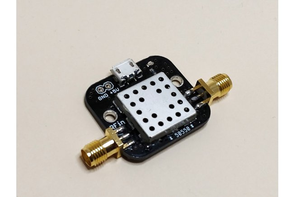
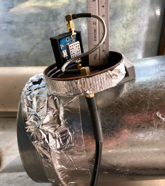
1420 MHz Hydrogen Line Low Noise Amplifier (Standard Version)
This amplifier is optimised for operation at 1420 MHz and provides more than 30 dB of gain with a noise figure typically below 1 dB, making it suitable for weak hydrogen line signal detection.
Power may be supplied via micro-USB or alternatively through a two-pin header accepting +5 V to +12 V DC.
This version does not include an integrated bias tee (a variant with this feature is available).
Key Characteristics
- Designed for hydrogen line reception at 1420 MHz
- USB power option plus alternative DC header input
- Typical noise figure under 1 dB (measured noise temperature approximately 91 ± 2 K, equivalent to ~1.16 dB NF)
- SMA female PCB edge connectors
- USB cable not supplied
Gain Response (Typical)
| Frequency | Gain |
| 500 MHz | 8 dB |
| 1000 MHz | 10 dB |
| 1200 MHz | 8 dB |
| 1300 MHz | 24 dB |
| 1420 MHz | 32 dB |
| 1500 MHz | 31.5 dB |
| 1800 MHz | 19 dB |
| 2000 MHz | 6 dB |
| 2400 MHz | 3 dB |
Maximum RF input: –10 dBm
Supply voltage: +5 V to +12 V DC


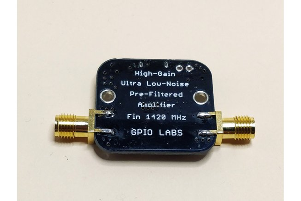
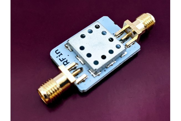
1420 MHz Pre-Filtered Low Noise Amplifier
This model incorporates pre-filtering ahead of the amplifier stage to improve selectivity around 1420 MHz. It provides approximately 32 dB of gain with a noise figure close to 1 dB.
Power options are identical to the standard model: micro-USB or +5 V to +12 V DC via header pins. A bias tee is not included in this version.
Main Features
- Integrated pre-filter centred at 1420 MHz
- USB or header-based DC supply
- Approximate 1 dB noise figure
- SMA female PCB edge connectors
- USB lead not included
Electrical performance and gain figures are similar to those listed for the standard amplifier above.
Maximum RF input: –10 dBm
Supply voltage: +5 V to +12 V DC

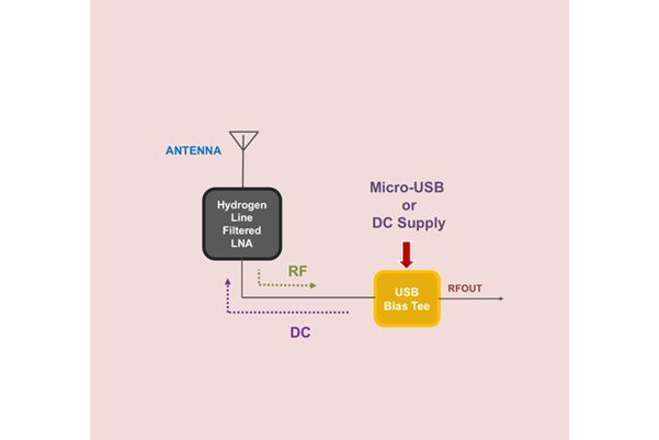
1420 MHz Pre-Filtered LNA with Integrated Bias Tee
This version includes an output bias tee, allowing DC power to be delivered via the RF coaxial cable from a compatible receiver or SDR. It may also be powered by micro-USB or via the DC header.
Important Safety Information
When powered through USB or the DC header, approximately +5 V DC will be present on the RF output connector. If the receiving equipment does not provide DC blocking or suitable protection, damage may occur. A DC blocking capacitor must be used if the downstream equipment cannot tolerate DC on its input.
If powering the amplifier from a receiver or SDR equipped with a bias tee, verify the supplied voltage with a multimeter. The acceptable range is +5 V to +12 V DC. Voltages above +12 V may cause permanent damage, while less than +5 V may result in unstable or insufficient amplification.
Features
- Pre-filtered design centred at 1420 MHz
- Built-in output bias tee
- USB or header power option
- Approximate 1 dB noise figure
- SMA female PCB edge connectors
- USB cable not supplied
Typical Gain Performance
| Frequency (MHz) | Gain (dB) |
| 100 | –23 |
| 200 | –9 |
| 300 | –2 |
| 400 | 0 |
| 500 | 3 |
| 1000 | 9 |
| 1200 | 35 |
| 1300 | 35 |
| 1420 | 34 |
| 1500 | 33 |
| 1800 | 21 |
| 2000 | –15 |
| 2400 | –5 |
Maximum RF input: –10 dBm
Operating supply range: +5 V to +12 V DC