At 20 kHz you’re really designing a resonant system, not just adding a tuner box. For your kind of radio astronomy / interferometry work, the most practical approach is a high-Q magnetic loop with integral tuning or a short vertical with heavy loading. I’ll outline both, but the loop is almost certainly the better route.
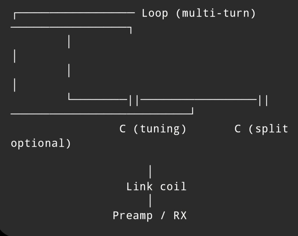
🌀 Option 1 — Tuned magnetic loop (recommended)
This behaves like a sharply tuned band-pass filter + antenna in one.
🔧 Basic layout
        ┌─────────────── Loop (multi-turn) ───────────────┐
        │                                                 │
        │                                                 │
        └───────||───────────────||───────────────────────┘
                C (tuning)       C (split optional)

                    │
                 Link coil
                    │
               Preamp / RX
📐 Design targets (20 kHz)
- Frequency: 20 kHz
- Loop diameter: 1–3 m (bigger = better SNR)
- Turns: 10–50 turns (depending on size)
- Inductance: typically 10–100 mH
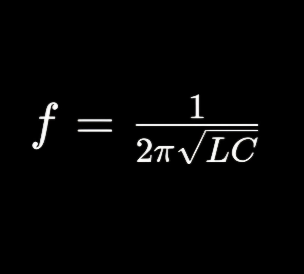
🧮 Resonance condition
For 20 kHz, typical combinations:
- L = 50 mH → C ≈ 1.26 nF
- L = 20 mH → C ≈ 3.2 nF
⚙️ Key components
1. Loop
- Multi-turn insulated wire (e.g. enamelled copper)
- Keep resistance low → improves Q
2. Capacitor
- High voltage (even on receive, Q can generate kV)
- Air variable or vacuum variable ideal
- Or switched polypropylene caps
3. Coupling (important)
- Small 1–2 turn link coil
- Loose coupling → preserves Q
🎯 Performance characteristics
- Bandwidth: often 100–500 Hz
- Very sharp tuning (you must retune frequently)
- Excellent rejection of broadband noise
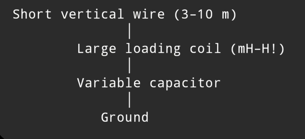
🧲 Option 2 — Short vertical + loading coil
This mimics a “traditional antenna + tuner”, but the tuner becomes huge.
🔧 Layout
     Short vertical wire (3–10 m)
              │
        Large loading coil (mH–H!)
              │
        Variable capacitor
              │
           Ground
⚠️ Reality check
- Coil can be physically large (ferrite rod or air-core drum)
- Efficiency is extremely low
- Very sensitive to ground losses
👉 This is closer to how VLF transmitters work, but for receive it’s usually inferior to a loop.
🔊 Front-end (this matters more than the antenna)
At 20 kHz, your limiting factor is usually noise + impedance mismatch, not radiation efficiency.
Best practice:
- High impedance preamp (JFET or op-amp front end)
- Place right at the antenna
- Differential input if possible
Common approach:
- Loop → link coil → high-Z buffer → SDR / soundcard
🧠 Practical build suggestion (tailored to you)
Given your interferometry work:
I’d suggest:
- Two identical tuned loops
- Spaced apart (baseline)
- Each with:
- fixed capacitor bank
- fine tuning (small variable cap or varactor)
Then:
- Feed into SDR (your SDRplay RSPduo setup fits perfectly)
- Do phase comparison in GNU Radio
⚡ A more experimental idea (you might like this)
Instead of high-Q tuning:
👉 Use:
- untuned loop
- very low-noise preamp
- digital filtering
Pros:
- no constant retuning
- wider bandwidth for transient work
Cons:
- lower SNR than resonant loop
🧾 Bottom line
- There’s no practical “box tuner” at 20 kHz
- The loop + capacitor is your tuner
- For your application:
👉 tuned magnetic loop + high-Z preamp = best performance