Andrew, yes it appears to be pretty much the type of power supply that I was referring to. Although I generally dislike Amazon listings as far as technical information details, the main pointers that apply here are the mention of the transformer, since it’s kind of the equivalent of the heart of a linear power supply able to bring the high line outlet voltage,110V US & I believe ~220V in the UK down to a more useable needed voltage such as 6-12 V or so. In the “OLD” days of vacuum tubes, these power supply transformers actually would raise the output voltage for use in tubes/valves to higher voltages, maybe as much as 300 to even higher 600-800 volts depending on the appliance whether a radio, transmitter, TV, stereo system etc.
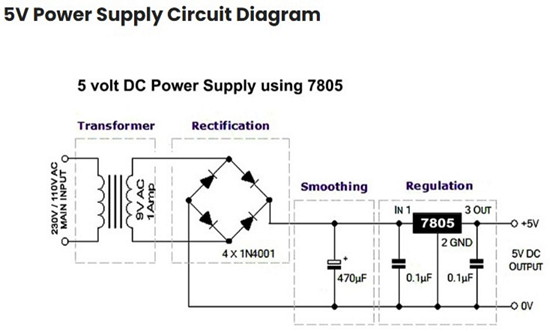
All modern semiconductor devices today of course require a voltage lowering type of transformers for the approximate voltages required. The next vital component in the linear power supply would be the rectifiers to convert the line AC transformer output voltages to what would be sort of a pulsed DC voltage with the AC cycle sine waves superimposed next to each other but now all with the same polarity. These voltage humps are then filtered/smoothed by capacitors mostly. As capacitors can average out the high to low voltage transitions when they charge during the high voltage sine hump and discharge during the zero voltage bottom of the half sine part of the variations.
The final necessary component then is the means of taking the lowered rectified voltage and controlling it to the desired exact voltage needed by the device and that is the voltage regulator circuit.
Two main types are used, the fixed voltage output regulators and the adjustable regulators that will control the rectified and filtered output DC voltages. They usually require an input voltage slightly higher than what is finally needed for the final regulated voltage output, say a 7-8 Volts input and then the regulator IC chip will then control it to the lower output voltage that it was designed to regulate. In the case of a popular chip component, a 7805 voltage regulator, those 7-8 volts into the 7805 will be regulated to always be an output of 5V as the final power supply output.
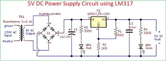
In this Amazon power supply the voltage regulator utilizes an adjustable LM317 regulator a variant adjustable regulator which is a bit different from the 7805 fixed output type in that although it is also a voltage regulator you can program it by a set of resistor dividers to set the final voltage you want it to regulate for it’s output.
Both types of regulators work great, and the fixed ones just go into the power supply circuit and you forget about the output voltages, it’s set by the device you use as in the 78xx series a 7805 will regulate to 5V, a 7812 to 12V etc.
With the LM317 the manufacturer just needs one semiconductor regulator part for different voltages they want and then they can choose the resistors values for the divider to program the final voltage needed, in the Amazon supply case they are obviously set for the 5V output.
The reason that switching supplies have been made popular now is because of efficiency in power use. As I described the input voltages for linear regulators need to be somewhat higher than the desired output you want in order to cover the current/amperage potentially needed by the attached equipment. This in part explains why the SDR Bias-T can only output a typical 4.5V or less as it is being powered by the 5V from the USB and then its attempt to regulate the output lowers it below that to 4.5V or less. For example if the equipment doesn’t use the full voltage current provided by the regulator, say the regulator can provide 1 amp at 5 volts or 5 watts but the equipment only uses 0.1 amp at 5 volts or only 0.5 watts the regulator has to get rid of the excess 4.5 watts of the 5 watts input to it and it does so by resistive heating. So those 4.5 watts are just wasted as heating up the regulator. This is not the case with a switching power supply as the components adjust the regulator input to just what is being required and not to the linear regulator excess power input that then just gets wasted as heat., The problem is that it uses switching circuitry that operate with frequencies into the dozens of kilohertz and can then produce many multiple harmonics of those frequencies which can reach up into the radio range and may cause either amplifier distortions possibly manifested as extra noise, depending on the design of the particular switching supply being utilized filtering of these very varied potential harmonics is difficult so some of them may ride along with the output voltage of the supply and into your equipment.
Hopefully this made some sense and explains why the basic linear supply function might provide a quieter LNA operation than potentially a switching supply.
For powering the Sawbird as you know, it has a separate supply input that can be used besides the one provided by the coax from the SDR bias -T output. So a separate line would need to be run up to the LNA secondary power input if you would like to use that one.
Remember the power would then also feed down through the coax from this other LNA power input and a voltage blocking connector might be needed at the SDR ant coax connector. Theoretically you can still power the LNA from the linear supply through the coax connector at the SDR coax if you use an external bias-T there isolating the SDR antenna from the linear power supply, and this would allow you to keep all your wiring to the outside LNA as is.
Hope this lengthy explanation helped.
Merry Christmas and have a Happy New Year
Adrian Clausell, 23/12/2025