Designing a simple cavity filter for 1420 MHz (the neutral hydrogen line at 1420.405 MHz) is very practical for radio astronomy front ends, especially to reduce out-of-band interference before amplification.
Below is a practical guide aimed at building a single-pole cylindrical cavity band-pass filter tuned to 1420 MHz.
1️⃣ Basic Principle
A cavity filter is simply a hollow metal resonator. At microwave frequencies, it behaves like a very high-Q tuned circuit.
At 1420 MHz:
\lambda = \frac{c}{f} \approx \frac{3\times10^8}{1.420\times10^9}
\approx 0.211 \text{ m}
So the wavelength is about 211 mm.
A quarter-wave resonator length is:
\lambda/4 \approx 52.8 \text{ mm}
That gives us the starting dimension.
2️⃣ Simplest Construction Type
The easiest home-build option is a:
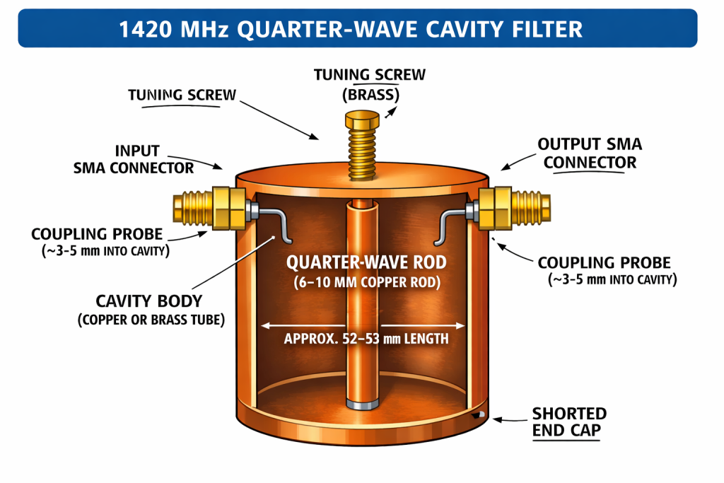
Quarter-wave coaxial cavity resonator
This consists of:
- A metal tube (outer conductor)
- A central rod (inner conductor)
- One end shorted
- The other end open
- Weakly coupled input and output probes
Think of it like a section of coax with one end shorted.
3️⃣ Practical Dimensions for 1420 MHz
Length (critical dimension)
Start slightly long and trim:
- Physical length ≈ 50–53 mm
- Expect to shorten slightly during tuning.
End effects will shift resonance slightly lower, so begin about 53–55 mm and trim down.
Diameter
Diameter affects Q but not frequency strongly.
Good practical choice:
- Cavity diameter: 40–80 mm
- Larger diameter → higher Q
- 50–60 mm is a nice compromise
Centre Rod
- 6–10 mm copper rod works well.
- Keep it rigid.
- The top end should be flat (not pointed).
4️⃣ Coupling
You need weak coupling for narrow bandwidth.
Method A — Probe Coupling (E-field coupling)
- Drill small holes near the open end.
- Insert short wire probes from SMA connectors.
- Start with ~3–5 mm penetration.
- Adjust depth to control bandwidth.
Method B — Loop Coupling (H-field coupling)
- Small loop made from semi-rigid coax.
- Insert near the shorted end.
Probe coupling near the open end is easier for first build.
5️⃣ Expected Performance
Single cavity gives:
- Bandwidth: ~5–15 MHz depending on coupling
- Q: 100–500 typical home build
- Insertion loss: 0.5–2 dB
- Out-of-band rejection: ~20–30 dB per cavity
For serious RFI suppression, cascade 2 or 3 cavities.
6️⃣ Fine Tuning
Best done with a NanoVNA.
Tune by:
- Adjusting rod length (file small amounts!)
- Adding a brass tuning screw at the open end
- Slightly adjusting probe depth
Target:
- Centre frequency: 1420.405 MHz
- Bandwidth: ~5 MHz is good for HI work
7️⃣ Construction Tips
- Use copper or brass tube.
- Ensure excellent electrical contact at the shorted end.
- Polish interior for higher Q.
- Avoid aluminium unless well bonded.
- Keep SMA connectors firmly grounded.
Even a copper plumbing end cap can work well.
8️⃣ Simple Alternative (Easier)
Instead of a cavity, you could use:
- 3-pole microstrip filter (PCB)
- Helical filter
- Commercial 1420 MHz SAW filter
But a cavity has:
- Much higher power handling
- Very low noise figure impact
- Better out-of-band rejection
9️⃣ For Your Radio Astronomy Setup
Since you’re working around 1420 MHz for hydrogen line work, placing the cavity:
Antenna → Cavity Filter → LNA → SDR
is ideal.
Never place a lossy filter after the LNA if trying to preserve system temperature.