
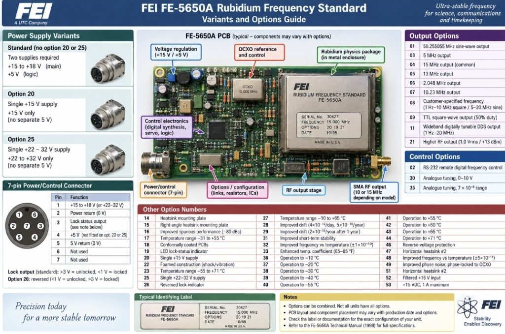
The official February 1998 FEI FE-5650A manual gives the following option numbers. Importantly, these are options that could be combined, rather than 40 completely separate models.
| Option | FE-5650A variant / feature |
|---|---|
| 01 | 50.255055 MHz sine-wave output |
| 02 | RS-232 remote digital frequency control |
| 03 | 5 MHz output |
| 04 | 15 MHz output |
| 05 | 13 MHz output |
| 06 | 2.048 MHz output |
| 07 | 10.23 MHz output |
| 08 | Customer-specified frequency: 1 Hz–10 MHz square / 5–20 MHz sine |
| 09 | TTL square-wave output, 50% duty cycle |
| 11 | Wideband digitally tunable DDS output, 1 Hz–20 MHz |
| 14 | Heatsink mounting plate |
| 15 | Right-angle heatsink mounting plate |
| 16 | Improved spurious performance, −80 dBc ±5 MHz from carrier |
| 17 | Temperature range −31 to +55°C |
| 18 | Conformally coated PCBs |
| 19 | LED lock-status indicator |
| 20 | Single +15 V supply rather than +15 V + +5 V |
| 21 | Higher RF output: 1.0 Vrms / +13 dBm |
| 22 | Foamed construction for severe shock/vibration |
| 23 | Temperature range −55 to +71°C |
| 25 | Single +22–32 V supply |
| 26 | Reversed lock indicator: <1 V = unlocked, >3 V = locked |
| 27 | Temperature range −10 to +65°C |
| 28 | Improved drift: 4×10⁻¹²/day, 5×10⁻¹⁰/year |
| 29 | Improved drift: 2×10⁻¹⁰/year after 1 year |
| 30 | Analogue tuning, 0–10 V |
| 31 | Improved short-term stability |
| 32 | Improved frequency-vs-temperature: ±1×10⁻¹⁰ |
| 33 | Enhanced temperature coefficient around 65–85°F |
| 35 | Analogue tuning, 7×10⁻⁹ range |
| 36 | Operation to −10°C |
| 37 | Operation to −20°C |
| 38 | Operation to −30°C |
| 39 | Operation to −40°C |
| 40 | Operation to −55°C |
| 41 | Operation to +55°C |
| 42 | Operation to +60°C |
| 43 | Operation to +65°C |
| 44 | Operation to +71°C |
| 46 | Reverse-voltage protection |
| 47 | Horizontal heatsink #2 |
| 48 | Improved frequency-vs-temperature: ±5×10⁻¹¹ |
| 49 | Improved phase noise; phase-locked to OCXO |
| 51 | Horizontal heatsink #2 |
| 52 | Filtered +15 V input |
| 53 | +15 VDC, 1 A maximum |
That’s the complete option list in the 1998 FEI manual.
The important ones for my particular 5650A
There are three fundamentally different power configurations:
Normal FE-5650A
- Pin 1 = +15 to +18 V
- Pin 2 = 15 V return
- Pin 4 = +5 V
- Pin 5 = 5 V return
Option 20
- Pin 1 = +15 V
- Pin 2 = return
- Pin 4 unused
- No separate 5 V supply
Option 25
- Pin 1 = +22–32 V
- Pin 2 = return
- Pin 4 unused
FEI explicitly confirms these three arrangements in the manual.