
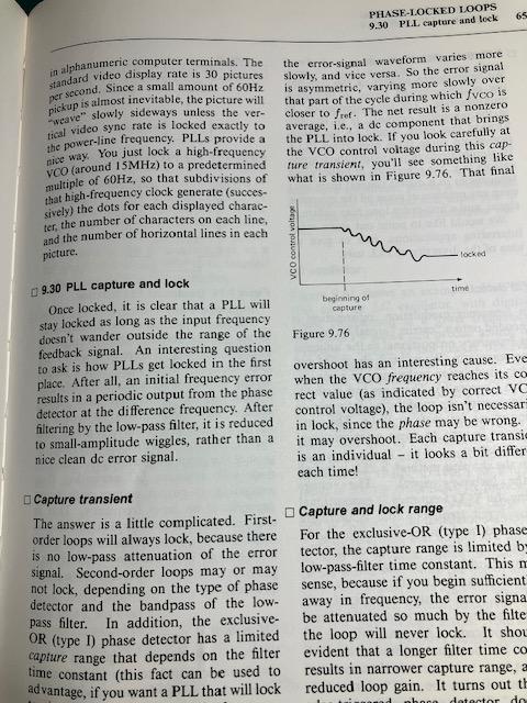
The page above is describing one of the most useful ideas in electronics: a Phase-Locked Loop (PLL). The terminology makes it sound considerably more complicated than the basic idea.
PLL in very simple English
Imagine you have two clocks ticking.
One is a reference clock that you trust. The other is an adjustable clock that you want to make follow the reference.
A PLL is an automatic system that continually asks:
“Is my clock running at exactly the same rate as the reference, and are the ticks occurring at the same instant?”
If the answer is no, it adjusts its own clock slightly faster or slower until they match.
Once they match, the PLL is said to be locked.
What is actually inside a PLL?
There are essentially three important parts:
1. A reference signal
This is the signal you want to follow. For example, it might be a very accurate 10 MHz reference.
2. A phase detector
This compares the reference signal with the PLL’s own signal.
It doesn’t just ask whether both are 10 MHz. It also compares when their cycles occur.
For example:
Reference:   |    |    |    |    |
             ^    ^    ^    ^    ^

PLL:           |    |    |    |    |
               ^    ^    ^    ^    ^

               slightly late
The phase detector detects that difference.
3. An adjustable oscillator
Usually this is a VCO — Voltage Controlled Oscillator.
Its frequency can be changed by changing a control voltage.
So the system works something like:
        Accurate reference
               |
               v
        +--------------+
        | Phase        |
        | detector     |
        +--------------+
               |
        "too fast" or
        "too slow"
               |
               v
        +--------------+
        | Low-pass     |
        | filter       |
        +--------------+
               |
        control voltage
               |
               v
        +--------------+
        |     VCO      |
        | oscillator   |
        +--------------+
               |
               +-----------> OUTPUT
               |
               +-----------> back to
                              phase detector
The important part is that the output is fed back and compared again.
It is therefore constantly correcting itself.
What does “phase locked” mean?
Suppose both signals are exactly 10 MHz.
That alone doesn’t necessarily mean they’re locked. One could be shifted in time:
Reference:  /\    /\    /\    /\
           /  \  /  \  /  \  /  \

PLL:          /\    /\    /\    /\
             /  \  /  \  /  \  /  \
They have the same frequency, but their peaks don’t occur at the same time.
A PLL adjusts the oscillator until the frequency and phase relationship settle down:
Reference:  /\    /\    /\    /\
           /  \  /  \  /  \  /  \

PLL:        /\    /\    /\    /\
           /  \  /  \  /  \  /  \
That’s the locked condition.
What is “capture”?
This is what the section in your photograph is discussing.
Imagine the reference is:
10.000 MHz
but the PLL oscillator initially starts at:
9.990 MHz
The signals continually slide past one another because their frequencies differ.
The PLL detects this difference and starts pulling its oscillator toward 10 MHz:
9.990 MHz
   |
   v
9.995 MHz
   |
   v
9.999 MHz
   |
   v
10.000 MHz
   |
   v
  LOCK
That process is called capture.
The wiggly line in Figure 9.76 is showing the control voltage hunting around while the PLL finds the correct setting.
It might do something like:
too high
   |
   v
too low
   |
   v
slightly high
   |
   v
slightly low
   |
   v
LOCKED
Rather like adjusting a shower: too hot → too cold → slightly too hot → slightly too cold → just right.
Capture range versus lock range
These two terms are easily confused.
The capture range means:
How far away from the correct frequency can the oscillator initially be and still manage to find and lock onto the reference?
The lock range means:
Once it has locked, how far can things drift before the PLL can no longer keep following the reference?
Often the PLL can remain locked over a wider range than the range from which it can initially acquire lock.
Why this matters for your frequency-standard work
This is particularly relevant to the sort of equipment you’ve been experimenting with.
Suppose you have an oscillator producing approximately:
10 MHz
and an extremely accurate reference also producing:
10 MHz
A PLL can continually compare the two.
If your oscillator gets very slightly ahead:
PLL detects: "We're getting ahead."

        ↓

Changes control voltage

        ↓

Oscillator slows very slightly
If it falls behind, the opposite correction occurs.
So the reference doesn’t necessarily have to generate the output signal itself. It can be used to continually discipline another oscillator.
That’s the idea behind many frequency-reference systems.
The shortest definition I’d use is:
A PLL is an electronic automatic-control system that makes one oscillator follow the frequency and timing (phase) of another reference signal.
And “PLL locked” essentially means:
“I’ve found the reference and I’m successfully following it.”