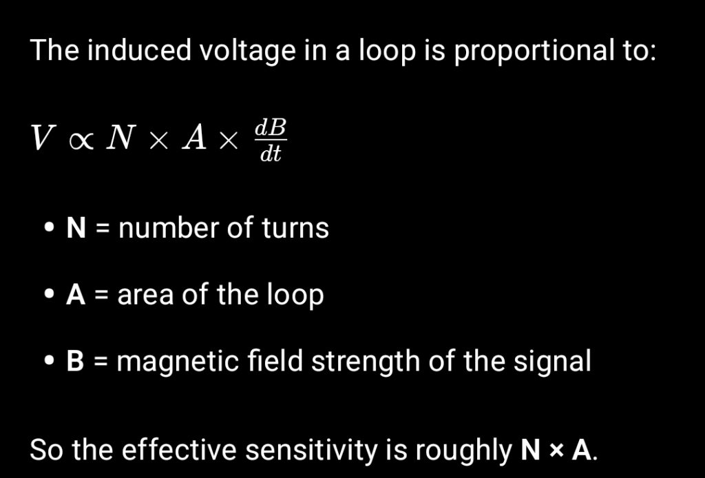
For a VLF loop antenna used to monitor Sudden Ionospheric Disturbances (SIDs), the received signal strength mainly depends on the loop area × number of turns, not simply the total amount of copper. The key parameter is the magnetic flux captured by the loop.
1. Basic principle
2. Large frame vs lots of wire
If you keep the same length of copper wire, you can either:
- Many turns on a small frame
- Fewer turns on a large frame
For VLF SID monitoring (typically 15–30 kHz transmitters):
A larger loop area usually performs better.
Reasons:
- Captures more magnetic flux
- Better signal-to-noise ratio
- Lower coil resistance
- Often higher Q when tuned
3. Practical trade-off
However, there are limits:
| Design | Pros | Cons |
|---|---|---|
| Large loop, few turns | Strong signal capture, good SNR | Lower inductance, may need larger tuning capacitor |
| Small loop, many turns | Higher inductance | More resistance, more thermal noise |
For SID work, people often find large loops with moderate turns work best.
Typical designs:
- 1–1.5 m square frame
- 20–40 turns
- Tuned with a capacitor to the transmitter frequency
4. A useful rule
If you have a fixed amount of wire:
Spread it over the largest practical frame first, then add turns until you reach the needed inductance.
Large area usually wins over tightly packed turns.
5. What many SID stations use
Common monitoring setups (including systems inspired by the Stanford Solar Center SID program):
- 1 m square wooden frame
- 20–30 turns of enamelled wire
- Tuned to transmitters like
- NAA VLF Transmitter (24.0 kHz)
- DHO38 VLF Transmitter (23.4 kHz)
6. A trick that improves performance
Use litz wire or multiple thin strands instead of a single thick conductor.
At ~20 kHz, skin effect starts increasing losses.
✅ Summary:
A bigger loop with fewer turns is generally better than a small loop with lots of turns when monitoring SIDs—provided you still get enough inductance to tune the loop.
For VLF SID monitoring (≈15–30 kHz), the most effective loop designs used by amateur and educational stations tend to converge on a similar “sweet spot” where loop area, inductance, and resistance are balanced.
Optimal loop antenna design for SID monitoring
Frame size
- 1.2–1.5 m square wooden frame
- Bigger loops collect more magnetic flux, improving signal-to-noise.
Number of turns
- 20–35 turns
This usually gives 5–15 mH inductance, which tunes nicely with common capacitors.
Wire
- 0.5–1 mm enamelled copper wire (or several thinner strands in parallel)
Why:
- Lower resistance
- Higher Q factor
- Better sensitivity
Tuning capacitor
To tune around 20–25 kHz, use:
- 5–15 nF variable capacitor
The resonant frequency follows the standard LC relation:
f=\frac{1}{2\pi\sqrt{LC}}
Example typical values:
| Inductance | Capacitance | Resonant freq |
|---|---|---|
| 10 mH | 10 nF | ≈15.9 kHz |
| 7 mH | 10 nF | ≈19 kHz |
| 5 mH | 10 nF | ≈22.5 kHz |
So 7–10 mH is a good target.
Amplifier
A high-impedance preamp right at the loop greatly improves results.
Typical options:
- JFET source follower
- Op-amp buffer
Orientation
Rotate the loop so the plane of the loop faces the transmitter.
Maximum signal occurs when the magnetic field lines pass through the loop.
Common transmitters monitored in Europe include:
- DHO38 VLF Transmitter – 23.4 kHz
- GQD VLF Transmitter – 19.6 kHz
- NAA VLF Transmitter – 24.0 kHz
These are strong and stable carriers ideal for detecting ionospheric disturbances.
✅ Summary of optimal build
- Frame: 1.3–1.5 m square
- Turns: ~25
- Wire: ~0.7 mm enamelled copper
- Inductance: ~7–10 mH
- Capacitor: 5–15 nF variable
- Add: high-impedance preamp
This configuration gives excellent SID sensitivity without excessive coil resistance.