WR-650 already covers 1.12–1.70 GHz, so 1.420 GHz sits comfortably in-band—you don’t need to resize the guide. What you do need is a simple, well-tuned coax-to-waveguide probe with a backshort (or a short straight section into a horn).
Here’s a practical recipe that works well at the H I line (1420.4058 MHz):
1) Key dimensions & checks
- WR-650 internal size: a = 165.1 mm (6.500″), b = 82.55 mm (3.250″)
- TE₁₀ cutoff: f_c ≈ 0.908 GHz → only TE₁₀ propagates at 1.420 GHz (TE₂₀/TE₀₁ ≈ 1.816 GHz).
- Free-space wavelength at 1420.406 MHz: λ₀ ≈ 211.1 mm
- Guide wavelength (TE₁₀) ca. 274.4mm.
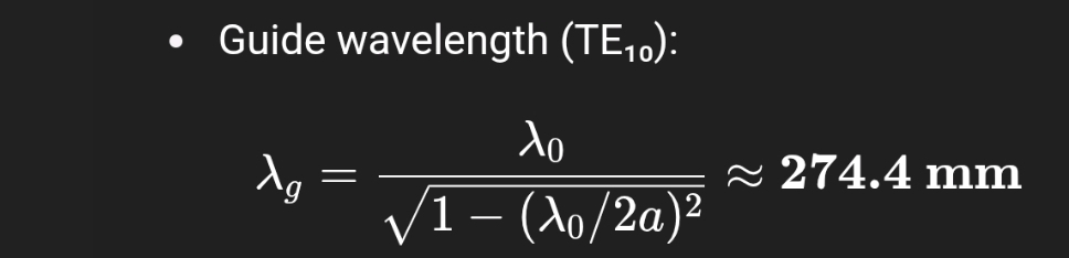
- Quarter-guide-wave: λg/4 ≈ 68.6 mm → this is your starting backshort spacing.
2) Build a coax probe + backshort transition
Layout (along the guide x-axis): [short-circuit plate] —— (λg/4) —— [probe] → open guide/horn
Placement across the guide:
- Drill through the broad wall (the large face).
- Put the probe on the centerline across the width (midway along b), where the TE₁₀ E-field is maximum.
Backshort distance (critical):
- From the shorting plate (or a solid end-plate) to the center of the probe: start at 68.5 mm.
- Provide ±10 mm of mechanical adjustment (slot holes or removable shim rings) for tuning.
Probe hardware:
- Use a 50 Ω N-female bulkhead (rugged) or SMA (if you prefer smaller hardware).
- Inner conductor becomes the probe: copper/brass rod or the connector’s pin extended.
- Diameter: 3–6 mm works well; keep it smooth and rigid.
Probe length (starting value):
- Start with L_probe ≈ 22–28 mm protrusion into the guide (from the inside of the broad wall).
- This is a safe, slightly-short starting point at L-band; you’ll lengthen/trim during tuning.
- Make it adjustable if possible (threaded boss + locknut, or a set-screw “trombone” tip).
Keep-out around probe:
- Leave ≥1 probe diameter clearance to the nearest edges/features.
- Deburr the hole; ensure good electrical contact of the connector flange to the guide (star washers or silver-paint if needed).
3) Straight section & horn (optional but recommended)
- Provide ≥ λg/2 ≈ 137 mm of straight guide from probe toward the aperture (if not immediately into a horn).
- A short pyramidal horn improves pattern and spillover. A simple flare that reaches an aperture ~0.8–1.0 λ₀ across (~170–210 mm) is already helpful; bigger is better if you’re not on a dish.
4) Tuning for S₁₁ and band-centering
Use a VNA (or an SDR + noise source + bridge if needed):
- Backshort first:
- Sweep S₁₁ around 1400–1450 MHz.
- Slide the backshort to bring the deepest return-loss dip near 1420.4 MHz.
- Probe length next:
- If the dip is above 1420 MHz → lengthen the probe slightly.
- If it’s below 1420 MHz → shorten it slightly.
- Aim for S₁₁ < −15 dB at 1420 MHz (−20 dB is very achievable).
- Fine match:
- Small tweaks (±1–2 mm) in backshort and probe length interact—iterate a couple of times.
- If you want more bandwidth or a deeper null, add a tiny capacitive hat (a small round washer) on the probe tip or use a second tiny tuning screw a few cm away on the broad wall.
5) LNA and system hookup (radio astronomy-friendly)
- Bolt a low-noise LNA (NF ≤ 0.5–0.7 dB at L-band) right at the probe port (or as close as mechanically possible) to keep system noise down.
- Weather-seal the connector and seams (EMI gasket + butyl tape).
- Use good coax to the receiver (short, low-loss; e.g., LMR-400 or 1/2″ Heliax if long).
6) Sanity checks & numbers you can trust
- With a = 165.1 mm, TE₁₀ cutoff is ~0.908 GHz; higher modes ~1.816 GHz → single-mode at 1420 MHz.
- λg/4 ≈ 68.6 mm is a robust starting backshort spacing.
- Probe length 22–28 mm (3–6 mm Ø) gets you close; expect ±5 mm of final tweak.
- Provide mechanical adjustment: slots/shims for the backshort, threaded probe if you can.
7) If you’re feeding a dish vs. a stand-alone radiator
- On a dish: Add a scalar ring or use a choked horn to reduce spillover and improve illumination efficiency; set phase center near the dish focus.
- Stand-alone: A pyramidal horn sized to ~1.5–2.0 λ₀ aperture gives ~12–16 dBi with decent beamwidth for sky surveys.
If you want, I can sketch a quick dimensioned drawing (probe, backshort, hole positions) and a tuning worksheet for logging S₁₁ vs. adjustments.