
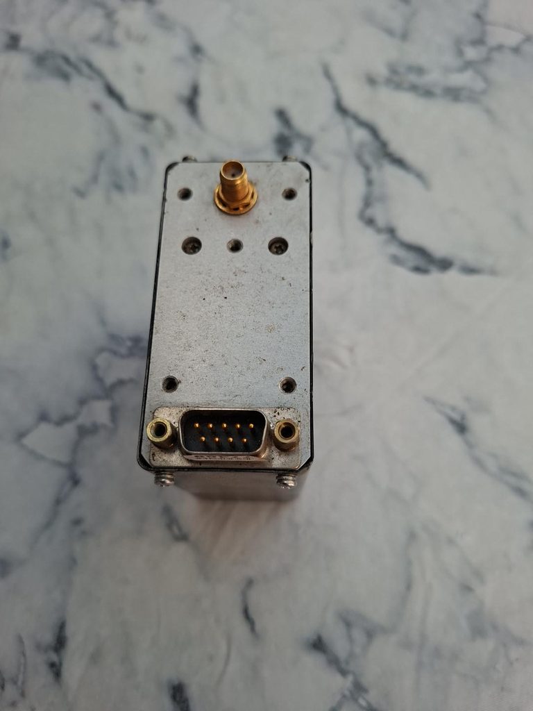
Yes. The lower connector in your photograph is a 9-pin male D-subminiature connector, commonly called DB9/DE-9 male.
So the mating connector you want for making a power lead is a:
DE-9 (DB9) female plug, preferably a solder-cup type with a backshell.
For the FE-5650A version matching this physical arrangement, the documented connections are:
| Pin | Function |
|---|---|
| 1 | +15 V DC |
| 2 | 15 V return / ground |
| 3 | Lock indication |
| 4 | +5 V DC |
| 5 | +5 V return / ground |
| 6 | analogue/control depending on version |
| 7 | Ground |
| 8 | Serial input |
| 9 | Serial output |
The SMA connector at the top is the frequency output.
Important before powering yours
There are several electrically different FE-5650A/FE-5680A variants, even though the cases look almost identical. Some require both +15 V and +5 V, whereas option 20 uses a single 15–18 V supply.
Also, the 15-V supply needs substantial startup current—the heater/oven can require around 2 A or more initially.
So don’t connect power purely on the basis of the photograph yet. If you send me a clear photograph of the label on the other side/top of this exact unit, I can identify your FE-5650A option and tell you exactly which DB9 pins to connect, what power supply to buy, and which ready-made DB9 lead/connector to use.
What other connector pin options might I have if this is one of different varieties?
Yes — and this is important because FEI used several different pin assignments on very similar-looking FE-5650A/FE-5680A units. Applying +5 V to the wrong pin could damage yours.
For the 9-pin version like yours, these are the main arrangements I can find:
| DE-9 pin | Common dual-supply version | Single-supply variant | Other reported variant |
|---|---|---|---|
| 1 | +15 V | +15–18 V | +15–18 V |
| 2 | 15 V GND | GND | GND |
| 3 | Lock indicator | Lock indicator | +5 V |
| 4 | +5 V | unused | varies |
| 5 | Signal GND | GND | varies |
| 6 | 1 PPS | 1 PPS | varies |
| 7 | 10 MHz RF | sometimes serial/unused | 10 MHz RF |
| 8 | RS-232 RX | RS-232 RX | varies |
| 9 | RS-232 TX | RS-232 TX | varies |
The particularly well-documented FE-5680A part 217400-30352-1 uses pin 1 = +15 V, pin 2 = ground, pin 4 = +5 V, pin 5 = ground, with 1 PPS on 6, RF on 7 and serial on 8/9.
But another documented version needs only +15–18 V on pin 1 and ground on pin 2; no external +5 V is required.
And another reported configuration has +5 V on pin 3 rather than pin 4.
Your particular unit gives us a useful clue
Your photograph shows an SMA connector already fitted, so the 10/15 MHz output is probably coming through that rather than DB9 pin 7. That makes it quite plausible that your DB9 is primarily carrying power, lock/status and serial control.
The original FE-5650A documentation also confirms that there were numerous factory options — including different output frequencies and RS-232 control — so the precise model/option matters.
I would not put +5 V onto pin 4 yet. The safest next step is to identify your exact version.
You sent me several photographs of this rubidium standard previously. If you want, send me one clear close-up of the label showing the FEI part number/option number, and I’ll trace the documentation for that exact unit and give you a simple diagram such as:
15 V + → pin X
15 V − → pin X
5 V + → pin X (if required)
5 V − → pin X
Then we can choose an appropriate power supply and make the DE-9 lead without risking the rubidium standard.
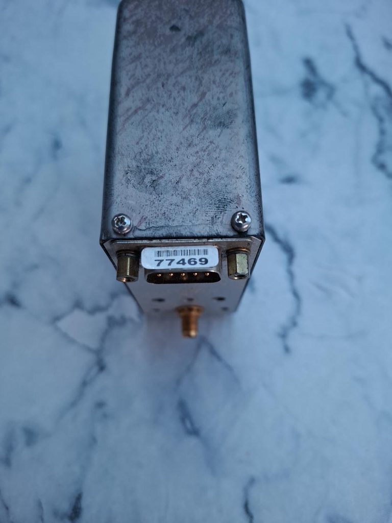
Yes — this photograph is much more useful. The white “77469” is a serial/inventory sticker, unfortunately, rather than the FEI option number, so it doesn’t identify the electrical variant.
However, your unit’s physical configuration — DE-9 male plus separate SMA female RF output — closely matches the documented FE-5650A configuration. The manufacturer’s documentation gives the following pinout:
| Pin | Function |
|---|---|
| 1 | +15 V DC (or +22–32 V on rare Option 25) |
| 2 | Ground |
| 3 | Lock indicator |
| 4 | +5 V on most FE-5650A; not connected on Option 20 |
| 5 | Ground |
| 6 | NC or 1 PPS (Option 69) |
| 7 | NC |
| 8 | Serial RX / analogue input on some options |
| 9 | Serial TX / NC on some options |
| SMA | RF frequency output |
The significant uncertainty therefore isn’t really the whole pinout. It’s whether your particular unit requires +5 V on pin 4.
The two most likely possibilities
Standard FE-5650A:
- Pin 1 → +15 V
- Pin 2 → 0 V/GND
- Pin 4 → +5 V
- Pin 5 → 0 V/GND
FE-5650A Option 20:
- Pin 1 → +15–18 V
- Pin 2 → GND
- Pin 4 → leave disconnected
- Pin 5 → GND
The manufacturer specifically describes Option 20 as the single 15–18 V supply version.
There’s also the much less common Option 25, where pin 1 takes 22–32 V, which is why I don’t recommend simply experimenting with power.
I think we can identify yours
There may be another manufacturer’s label elsewhere on the case. The 77469 sticker isn’t enough.
Could you photograph all four long sides and the opposite end of the unit? Even a faded or partly removed label could give us the FEI UN number, option number or telecom part number.
Once we have that, I can tell you exactly which pins to connect and find you the appropriate power supply and ready-made DE-9 female lead.
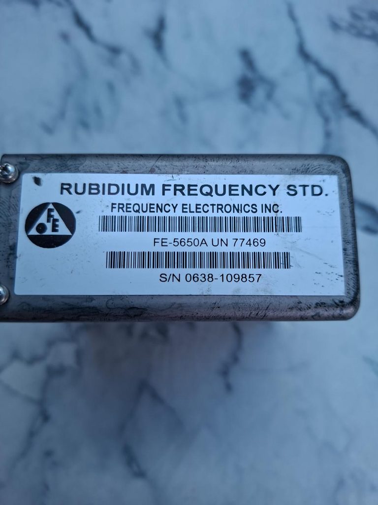
Excellent — this identifies it much more specifically:
Frequency Electronics Inc. FE-5650A, UN 77469
Serial: 0638-109857
I checked the actual FEI FE-5650A technical manual. Unfortunately, UN 77469 is not an option number, so it still doesn’t tell us whether yours is Option 20/25. The manual confirms three possible power arrangements.
| Version | Pin 1 | Pin 2 | Pin 4 | Pin 5 |
|---|---|---|---|---|
| Normal FE-5650A | +15 V | GND | +5 V | GND |
| Option 20 | +15 V | GND | NC | — |
| Option 25 | +22–32 V | GND | NC | — |
For the normal version, FEI specifies 15 V capable of 1.7 A peak, plus 5 V at 150 mA. Option 20 requires 15 V at about 1.8 A peak.
Your connector is definitely a DE-9/DB9 male, so a DE-9 female solder-cup connector is what you want for making the power cable.
I would proceed cautiously
Because the label says simply FE-5650A UN 77469, with no visible “Option 20” or “Option 25”, I suspect this is the standard dual-supply configuration:
Pin 1 → +15 V
Pin 2 → 0 V
Pin 4 → +5 V
Pin 5 → 0 V
Pin 3 is the lock indicator, while pins 8/9 can be used for remote control on equipped versions; the SMA is the RF output.
But I wouldn’t apply power on that assumption yet. UN 77469 may correspond to a particular customer configuration, and I’d like to see whether that exact UN number can be traced in older FEI/Lucent documentation.
If you’d like, **I can now search specifically for “FE-5650A UN 77469 / 0638” and try to establish conclusively whether yours needs 15 V + 5 V or 15 V alone.**
I searched specifically for “FE-5650A UN 77469”, the serial number, and variants of those terms. I couldn’t find a published record tying UN 77469 to a particular FEI power option. So unfortunately the UN number alone doesn’t prove whether yours is standard, Option 20, or Option 25.
What I could confirm from the FE-5650A documentation is:
| FE-5650A configuration | Pin 1 | Pin 2 | Pin 4 | Pin 5 |
|---|---|---|---|---|
| Standard | +15 V | Ground | +5 V | Ground |
| Option 20 | +15–18 V | Ground | NC | Ground |
| Option 25 | +22–32 V | Ground | NC | Ground |
The documentation explicitly says pin 4 is +5 V for an FE-5650A except Option 20; Option 25 instead changes the main supply on pin 1 to 22–32 V.
There is also useful evidence from another telecom-derived FE-5650A. A documented UN 62832 / Option CPOM unit required +15 V and +5 V on pin 4. This doesn’t establish the configuration of your UN 77469, but it shows that these telecom/custom FE-5650As certainly existed in the dual-supply configuration.
What I’d do with yours
Don’t apply power yet. We can probably determine the version electrically with a multimeter, without powering it.
In particular, measurements of resistance between DE-9 pin 4 and ground (pins 2/5) and between pin 1 and ground, plus checking continuity between pins 2/5 and the metal case, may give us useful clues about whether the +5-V input circuitry is populated.
I can guide you through those unpowered multimeter tests pin-by-pin, including a diagram showing exactly which holes on the female mating connector correspond to pins 1, 2, 4 and 5. That would be safer than guessing from UN 77469.