
This is used communications hardware. Hand-written on cardboard box is 10 MHz.
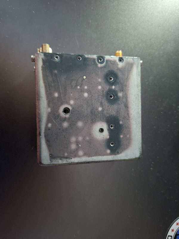
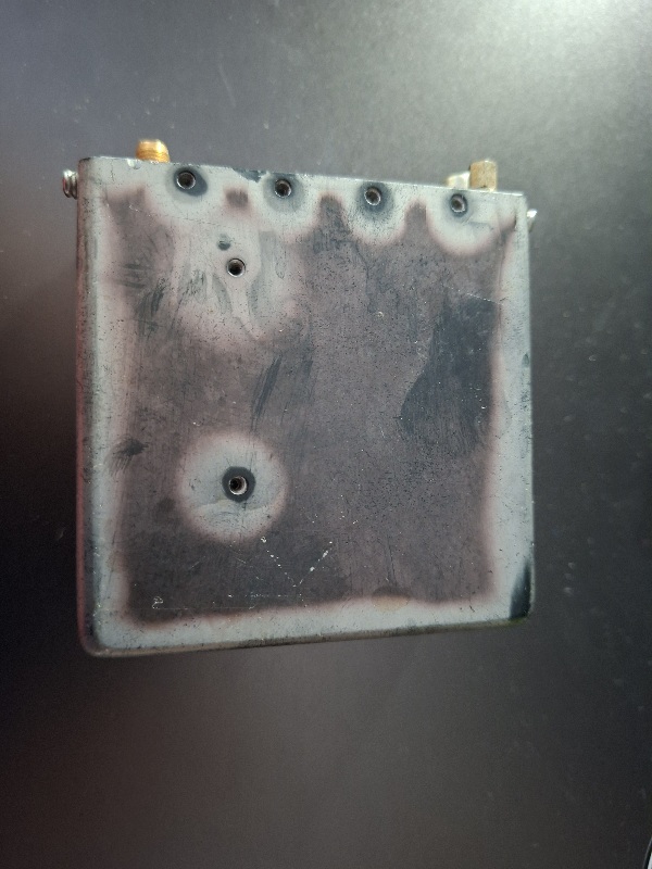
THE FOLKOWING COMES FROM AN ANALYSIS OF THE PHOTOS ABOVE BY CHATGPT, AND REQUIRES CONFIRMATION EXPERIMENTALLY:
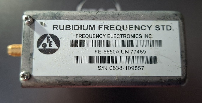
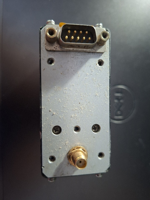
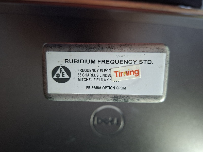
You have a Frequency Electronics Inc. (FEI) FE-5650A rubidium frequency standard, marked Option CPOM, serial number 0638-109857. The case has an SMA RF connector and a 9-pin D-sub connector. The additional sticker appears to be from Timing and describes it as a “55 Channels …” unit, suggesting this particular assembly may have been supplied as part of a timing/GPS-disciplined system rather than simply as a bare oscillator.
The important point is: don’t apply power to the DB9 yet. FE-5650A units exist in a number of configurations, and the connector pinout, supply voltage and output frequency can differ between variants. We should establish the pinout for FE-5650A / option CPOM before experimenting.
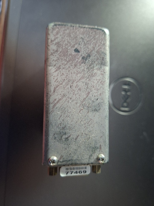
From the photographs, it looks physically complete and in quite reasonable condition for an ex-equipment rubidium module. The SMA is very likely the frequency output, while the DB9 will normally carry power and may also carry things such as lock/status and serial control.
I suggest we do this in three stages:
- Identify the exact FE-5650A CPOM pinout and electrical requirements.
- Work out a safe bench-test setup — power supply, current limit, DB9 wiring and how to tell when the rubidium lamp/servo has locked.
- Once we’ve proved it works, design your complete atomic-clock project around it: buffered 10 MHz reference outputs, frequency counter/display, 1-PPS/clock generation and enclosure.
I found information specifically for the FE-5650A Option CPOM, including reports from people using essentially the same variant as yours. That is much more useful than the generic FE-5650A manual.
Your DB9 pinout
The best-documented CPOM pinout is:
| DB9 pin | Function | What to do initially |
|---|---|---|
| 1 | +15 V DC | Connect +15 V supply |
| 2 | 15 V return / ground | Connect 15 V negative |
| 3 | LOCK/BITE indication | Measure only initially |
| 4 | +5 V DC | Connect +5 V supply |
| 5 | +5 V return | Connect 5 V negative |
| 6 | Analogue VCO/EFC-related signal | Leave disconnected |
| 7 | Ground | Can leave disconnected initially |
| 8 | Serial input, TTL level | Leave disconnected initially |
| 9 | Serial output, TTL level | Leave disconnected initially |
This is especially convincing because a March 2026 experimenter reports having an FE-5650A Option CPOM, albeit a 15-MHz example, and independently confirmed pins 2/5/7 as grounds and pins 8/9 as TTL-level serial.
⚠️ One particularly important point
Do not connect pins 8 and 9 directly to a conventional ±12 V RS-232 port.
Although some FEI documentation refers to RS-232, the CPOM variant appears to use TTL-level serial signalling on these pins. A recent owner specifically confirmed this experimentally.
A USB-to-TTL serial adapter would therefore be the sensible interface later.
Power supplies
For the first test I’d use two regulated bench supplies:
15.0 V → pin 1
0 V → pin 2
and
5.0 V → pin 4
0 V → pin 5
The 15-V supply needs considerably more capacity than you might expect. One detailed CPOM investigation found that the unit requires more than 1 A during warm-up, and reports startup current somewhat above 2 A, before falling substantially as it warms.
I’d therefore use approximately:
15 V, ≥3 A supply
5 V, ≥1 A supply
rather than trying to run it from a little wall adapter initially.
FEI describes the FE-5650A family as a compact digitally programmable rubidium standard capable of frequencies between 1 Hz and 20 MHz depending upon configuration.
What I think your particular unit outputs
There is a very interesting clue on your label:
FE-5650A UN 77469
and your other sticker says:
“55 CHANNELS LINDBER…”
Your unit therefore appears to be a telecommunications/timing-system pull. That’s consistent with the history of many CPOM units.
And importantly, many of the newer telecommunications FE-5650As were configured for 15 MHz, rather than the 10 MHz commonly associated with laboratory frequency standards.
So I would not assume yours is 10 MHz.
We’ll simply measure it.
Your first power-up
I’d make the test extremely simple.
             FE-5650A CPOM
             DB9 connector

15 V +  ───────── PIN 1
15 V -  ───────── PIN 2

LOCK meter ────── PIN 3

 5 V +  ───────── PIN 4
 5 V -  ───────── PIN 5

                PIN 6  NC
                PIN 7  NC
                PIN 8  NC
                PIN 9  NC


       SMA RF OUTPUT
             │
             │ coax
             ▼
       Oscilloscope /
       Frequency counter /
       SDR
Set the 15-V supply current limit to about 2.5–3 A for the initial experiment.
I’d set the 5-V current limit to about 1 A.
Then switch on both supplies and watch the current.
Don’t be alarmed if the unit gets warm. The rubidium physics package and oven have to reach operating temperature. Owners specifically report that these units run hot.
How we’ll know it has locked
Pin 3 is the BITE/LOCK output.
For the CPOM pinout, it is documented as LOW when locked.
So I’d put a multimeter between:
pin 3 → meter +
pin 2 → meter −
and observe what happens during warm-up.
Don’t put an LED directly between it and a supply yet; let’s establish what your particular unit is doing first.
At the same time, connect the SMA output to an oscilloscope or frequency counter.
One documented CPOM produced approximately a 3 V peak-to-peak 15-MHz waveform.
One thing I would not do yet
Don’t try programming it.
The CPOM version is rather different from some earlier programmable FE-5650As. Evidence indicates that the newer architecture has a much smaller frequency-adjustment range than the older broadly programmable versions. One recent experiment found that the CPOM could be finely calibrated but couldn’t simply be changed from 15 MHz to 10 MHz by software.
That’s not a problem for your atomic-clock project. If yours produces 15 MHz, we can derive 10 MHz, 5 MHz, 1 MHz, 100 kHz, 10 kHz, 1 kHz and 1 PPS electronically while retaining the rubidium stability.
What I’d do next
I suggest we don’t open the rubidium unit yet.
First make a DB9 breakout lead and perform the test above. If you send me a photograph of the DB9 plug/cable or breakout board you’re intending to use, and tell me what bench power supply you have, I can show you exactly which wires go where.
Once we’ve established that it locks and whether that SMA is 10 MHz or 15 MHz, I can design the next part as a proper project for you: FE-5650A → frequency divider/synthesiser → multiple buffered 10-MHz outputs + 1-PPS → microcontroller → LCD showing atomic-clock time, all in a suitable enclosure.