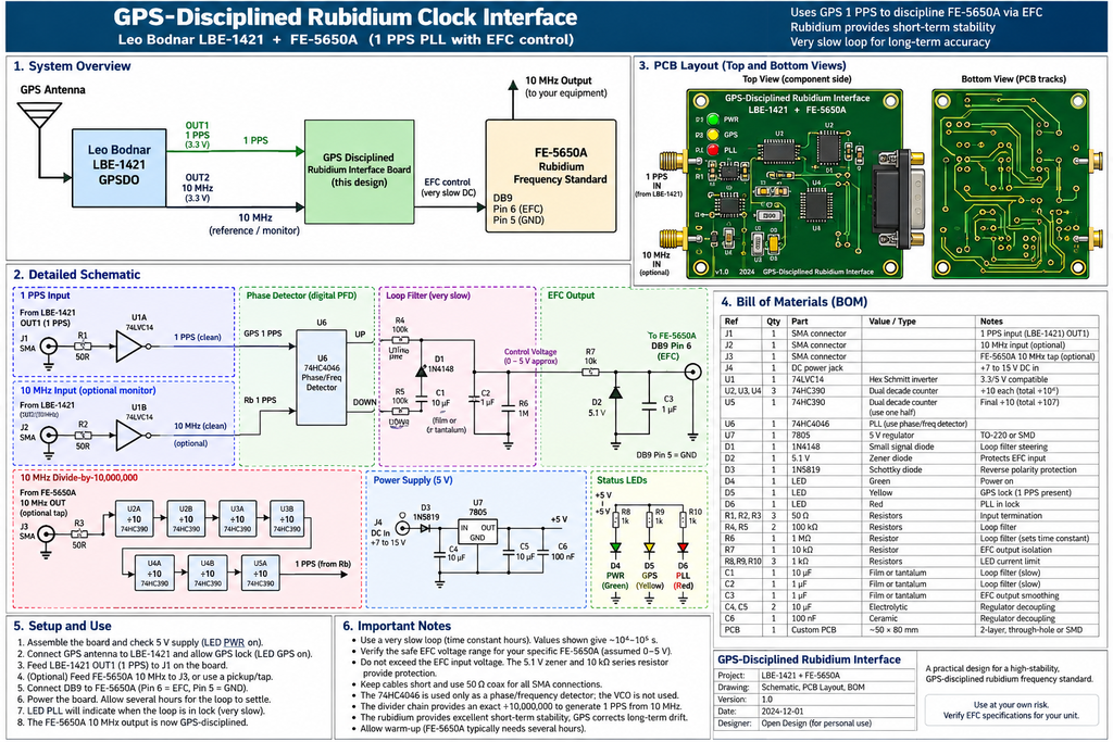
You can use the 1 PPS as the long-term GPS timing reference, while allowing the FE-5650A rubidium oscillator to provide the very stable short-term frequency.
Conceptually:
GPS antenna
     |
     v
+-----------+
| LBE-1421  |
+-----------+
     |
    1 PPS
     |
     v
+----------------+
| Phase detector |<----- divided-down FE-5650A
| / PLL          |       output (10 MHz -> 1 Hz)
+----------------+
     |
 very slow correction
     |
     v
FE-5650A EFC
     |
     +--------> 10 MHz GPS-disciplined
                 rubidium output
The key point is that you cannot feed 1 PPS directly into the FE-5650A EFC input. The PLL needs to compare the GPS 1 PPS with a 1 PPS signal derived by dividing the FE-5650A’s 10 MHz output by 10,000,000.
The phase error between those two 1 PPS signals is then filtered and converted into a slowly changing DC voltage for the FE-5650A’s EFC input.
This is actually a very attractive way of making the GPS-disciplined rubidium atomic clock we discussed: FE-5650A = flywheel/short-term stability; LBE-1421/GPS = long-term accuracy; PLL = keeps the two aligned.
SUGGESTED ARRANGEMENT BY CHATGPT:
Yes. I can show you how to build it, but I would do it in two stages. The first stage is completely safe and lets us prove that the GPS and rubidium standards agree before connecting anything to the FE-5650A’s EFC.
The LBE-1421 is particularly convenient because Output 1 can provide genuine GPS-derived 1 PPS, while Output 2 can simultaneously provide a programmable frequency such as 10 MHz.
Stage 1 — compare them without controlling the rubidium
You need to turn the FE-5650A’s 10 MHz into 1 PPS:
                     GPS antenna
                          |
                          v
                   +-------------+
                   |  LBE-1421   |
                   +-------------+
                          |
                    OUT 1 = 1 PPS
                          |
                          |------------------+
                                             |
                                             v
                                      +-------------+
                                      | Phase       |
                                      | comparator  |
                                      +-------------+
                                             ^
                                             |
FE-5650A                                    1 PPS
10 MHz output                                 |
     |                                        |
     v                                        |
+----------------------+                      |
| Divide by 10,000,000 |----------------------+
+----------------------+
The LBE-1421 documentation confirms that Output 1 can be switched to 1 PPS, rather than merely programming it to 1 Hz. That’s the setting I’d use.
The divider
This sounds complicated but isn’t. We need:
10,000,000 Hz
      ↓ ÷10
1,000,000
      ↓ ÷10
100,000
      ↓ ÷10
10,000
      ↓ ÷10
1,000
      ↓ ÷10
100
      ↓ ÷10
10
      ↓ ÷10
1 Hz
Seven decade divisions.
One straightforward way is two 74HC390 dual-decade counter ICs, although I’d probably build this with a small microcontroller/CPLD or dedicated divider because it makes the complete clock much easier.
Then the PLL
The two 1-PPS signals go into a phase detector:
GPS 1 PPS ---------------------+
                               |
                               v
                         +-----------+
                         | Phase     |
                         | detector  |
                         +-----------+
                               |
                        phase error
                               |
                               v
                       +---------------+
                       | Very slow     |
                       | loop filter   |
                       +---------------+
                               |
                      correction voltage
                               |
                               v
                       FE-5650A EFC
The loop should be extremely slow. We don’t want GPS continuously pulling the rubidium oscillator around. The rubidium provides the excellent short-term stability; GPS merely removes its very small long-term frequency error.
But don’t connect that last wire yet
For your particular FE-5650A, the information you’ve obtained identifies DB9 pin 6 as EFC/VCO Analog, but importantly your own documentation currently marks this function as unconfirmed, and the seller’s information says to leave it disconnected during normal operation.
Before designing the analogue output stage, we need to establish two numbers:
1. Allowed voltage range on pin 6
and
2. EFC sensitivity, e.g. how many parts in 10¹¹ the oscillator moves per volt.
Without those, I don’t want you applying a voltage to pin 6.
There’s an easier first experiment with equipment you already have
You don’t actually need to build the PLL yet.
Connect:
LBE-1421 OUTPUT 2
set to 10 MHz
        |
        v
Rigol CH1


FE-5650A 10 MHz
        |
        v
Rigol CH2
Let both warm up and lock.
The LBE-1421 specifies GPS-locked long-term stability approaching 1 × 10^-12, making it an excellent reference against which to measure the FE-5650A.
Put the Rigol into XY mode or display both traces and trigger from the Bodnar. If the rubidium is exactly 10 MHz relative to the GPSDO, their relative phase will remain essentially stationary. If it’s slightly high or low, you’ll see the FE-5650A waveform slowly walk across the Bodnar waveform.
That measurement is actually the first thing I’d do before building anything.
Once we’ve measured that, I can design you a complete little LBE-1421 + FE-5650A GPS-disciplined rubidium PLL board, including the divider, phase detector, very-slow loop filter, protected EFC output and LEDs for Rb LOCK / GPS LOCK / PLL LOCK. The only thing I don’t want to guess is the safe EFC range of your particular FE-5650A.
PROPOSED PLL BOARD LAYOUT FOLLOWING INITIAL TESTS ABOVE FROM CHATGPT:
Validity of this design is not proven.