
This feed has been shown to be very effective by Alex Pettit (see SARA mailing list). Why is it so good?
FROM ADRIAN KLAUSSEL, FIRST PUBLISHED ON THE SARA MAILING LIST AUGUST 2026:
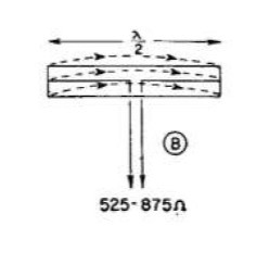
Unfortunately without actual official published circuit diagrams it’s difficult to know for certain but it does not appear that a simple dipole on either the Kraken discovery feed or even the feed on the scope in a box dish is what is used. Technically it is called a multi element folded dipole and it has no reflector. it is related to the diagram configuration B which shows a 3 element folded dipole as a representative form of the actual 5 element folded dipole feeds on these dishes. This comparison is with both the SIAB feed and the Discovery Feed indicated inside the blue circle for the Kraken close up image.
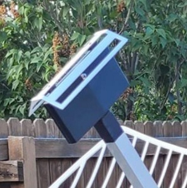


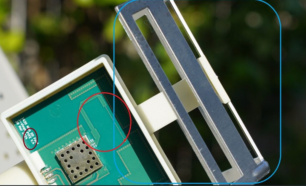
The most important clue to this arrangement is the matching network inside the red circle for the Discovery feed.

You can see from the impedances listed at the bottom of diagram B that the folded‑dipole configurations sit at several hundred ohms, while the SDR or LNA inputs are a nominal 50 Ω. The very thin microstrip trace coming from the antenna reflects this high impedance, since microstrip width is inversely related to the characteristic impedance of the trace. Where that thin trace transitions into a much wider one, you’re looking at the transmission‑line matching network that steps the several‑hundred‑ohm feed impedance down to 50 Ω before entering the LNA under the shield. In other words, the antenna’s native impedance is nowhere near 50 Ω, so the PCB uses a microstrip transformer to make the system compatible.
In any case the antenna obviously is nowhere close to a dipole impedance of near 50 ohms natively.
So why utilize this type of antenna feed? The answer is because a multi‑element folded‑dipole bent feed gives you a broadband, high‑impedance radiator with a clean, wide beam that illuminates a parabolic dish far more efficiently than any 50‑ohm dipole ever could. The high native impedance shapes the current distribution for better gain and pattern stability, the bow‑tie/bent geometry also helps in forming the beam to reduce spillover and improve edge illumination and in addition the multi‑element folding smooths the impedance across a wide band. The thin‑to‑wide microstrip section then is simply the transformer that steps those several‑hundred‑ohm feed impedances down to 50 Ω for the LNA. So this type of feed is used because it is broadband, efficient, mechanically robust, and produces the correct illumination pattern for dishes even though its native impedance is nowhere near 50 Ω. Finally the very useful information that is also silkscreened on the PC board within the maroon circle, “PTFE” also indicates that the board design is implemented in a Teflon type dielectric substrate instead of the inferior FR4. This substrate board material is also known by the brand name Rodgers Duroid and is the type of PC board that is used for all quality microwave circuits due to its superior low loss and dielectric constant which is desirable in the frequency range of these circuits. Discussions comparing the active devices used in the Kraken LNA to those in the NooElec Sawbird HI and the potential performance advantages of the Kraken NF device values that are suggested by their datasheets—can be found in a search of previous forum posts by Marcus Leech and others who have described the components for each of the two designs.
Adrian